Graphics Links at Holmes3D.net
DCEL stands for Doubly-Connected Edge List. A DCEL is a data structure for efficiently storing topological information about a 2D surface (Possibly located in 3D space). The surfaces so represented are usually considered to be equivalent to planar subdivisions, although not every implementation will necessarily be able to store a true planar subdivision. (See Advanced Issues below).
|
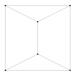
The surface in question is composed of faces (polygons), edges (boundaries between two adjacent faces), and vertices (boundaries between two adjacent edges). Edges are only permitted to touch each other at vertices, which means that edges never cross each other. In 2D this is a "subdivision" of the plane: the plane is divided into pieces by edges, and every one of those pieces is a face. |
|
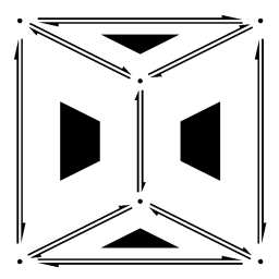
We will be concerned with the surface located in 3D space. When we move to 3D, we still have a 2D surface, it just is no longer constrained to lie in the 2D plane. Our surface is still constrained to be manifold. This means that every edge is like an edge in the 2D surface in that it separates two faces (You can never have three or more faces sharing the same edge). We will also constrain our surface to be orientable, that is, every face has an inside and an outside (equivalent to looking at it from above or below the 2D plane) and all neighboring faces have consistent insides and outsides. This type of surface is familiar to most 3D graphics users as a polygon mesh. (Or, if we further limit every face to having three sides, as a triangle mesh). |
|
A DCEL data structure gives us a way to describe a polygon mesh in such a way that it is easy to find neighbors of vertices, edges or faces without searching through long lists of polygons. This fast access is very useful, as we will see.
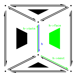
The DCEL data structure is centered around the concept of the edge, but in a slightly non-intuitive fashion. Instead of representing an edge directly, every edge is composed of two "half-edges". The two half-edges that compose an edge are said to be "twins" of each other, and store pointers to each other. Each half-edge stores a pointer to its origin, but not to its destination. The destination of a given half-edge h can be found by look at the origin pointer of h's twin. This organizational strategy means that every half-edge has an orientation, and that orientation is always opposite to the orientation of its twin.
|
|
A half-edge has an "outside" that touches a face and an "inside" that touches its twin. We are free to choose which of these is which, but we will choose the "outside" to be the left side, viewing the directed half-edge from the top (For reasons to be seen later). Now we can see that every half-edge has a single face that touches it. We will store a pointer to this face in the half-edge. |
Note that the name Doubly-Connected Edge List is somewhat deceptive, and not very descriptive. The same data structure is sometimes known as a Halfedge, Half-Edge, or twin-edge data structure, all of which are better names. The original DCEL structure used oriented edges with two vertex pointers per edge, instead of half-edges, and was thus not as useful or as efficient. The basic idea was similar however, and the more efficient structure retained the original name.
The DCEL data structure consists of three types of objects; vertices, half-edges, and faces. These objects primarily consist of "pointers" to other DCEL objects. These could be literal C/C++ pointers that contain memory addresses of other objects, or could be handles, array indices, or other types of addressing. The essential quality is that they allow direct access to the pointed-to object, without searching. For the sake of description I use the word pointer to refer to this type of reference and the C++ arrow notation to refer to a particular instance's pointer (e.g. h->origin is the origin pointer of the HalfEdge h).
Note that each of the objects is of fixed size. Even for meshes composed of triangles, quadrilaterals and general polygons, the objects contain the same amount of information per object.
|
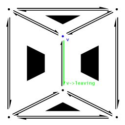
A Vertex object contains a single DCEL pointer, named "leaving", to a HalfEdge object. This pointer points to a single HalfEdge that has this Vertex object as its origin. If multiple HalfEdges have this Vertex object as their origin, the leaving pointer can point to any one of them arbitrarily. |
|
|
The HalfEdge object contains a pointer to a Vertex, named "origin", a pointer to a Face named "face", and two pointers to HalfEdges, one named "twin" and one named "next". The origin is the vertex from which the HalfEdge starts. The face is the face on the "left" side of the HalfEdge, while the twin pointer points to the HalfEdge on the "right" side of the HalfEdge that completes its edge. The "next" pointer points to the HalfEdge that starts from h->twin->origin and ends at the next vertex in h->face, traveling counterclockwise around the boundary. This pointer allows us to traverse a polygon, by following next pointers until we arrive back at the HalfEdge we began at. |
|
|
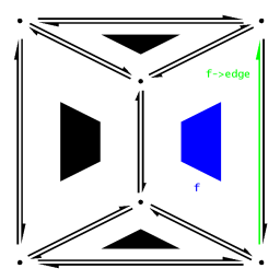
A Face object contains a single DCEL pointer, named "edge", to a HalfEdge object. This pointer points to a single HalfEdge that has this Face object as its face. This HalfEdge can be any one of the Face object's boundary HalfEdges. |
|
A DCEL data structure is a collection of Vertex, HalfEdge, and Face objects, with "correct" pointers between the objects. In a minimal case this is enough. We will add three more ideas to these collections.
In many uses of a DCEL data structure we will want to apply some operation to all Vertex, HalfEdge, and/or Face objects. Therefore, we need some method of iteration that will allow us to touch each object of each respective type once and only once. In practice this means the objects are in an array, linked list, or some other type of structure that allows ordered traversal. Depending on our specific need this structure may need to be dynamic, allowing insertion and deletion of objects.
|
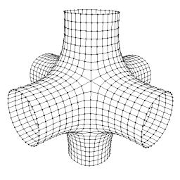
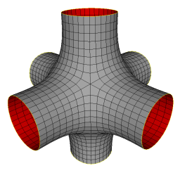
We have, until now, avoided describing the boundary of a mesh. We have described all edges as having a face on either side. However, intuitively, if we have a boundary we will have edges that have a face on one side and nothing on the other side. To keep the structure consistent we introduce a special "infinite face"; a Face object that is not traversed by the iterators and is always accessible for comparison and testing. This face is the face on the "outside" of all boundary edges. Depending on the intended use of the DCEL structure it may or may not store an edge pointer, because it may not be meaningful to try to traverse the edges of the infinite face For instance in the image to the right the edges of the infinite face form six separate pieces, one chain each where each arm of the mesh opens out. |
|
For most applications we will want some further type of data associated with some or all of our DCEL objects. This data may be something that is complex enough to calculate that we want to cache it with the object (e.g. the normal of a face or the normal of a vertex), or may be temporary data required as part of some algorithm on the structure (e.g. an "already visited" tag when flood-filling a surface). There are numerous ways to handle associated data, which largely depend upon the data in question. Normals, for instance, may be so common that we just add them to our objects, or to sub-classes of base objects. Temporary data may be so rarely used that we feel it worthwhile to set up a separate hash table to associate DCEL objects with the temporary data. I will generically say that data D is associated with a DCEL object O when given O, we can find D in constant time. Note that this does not necessarily mean that given D we can find O, although we may also create that association if needed.
The simple description above sidesteps several important issues for DCEL structures, in large part because the structure as presented is sufficient for our purposes in 3D graphics. The following issues may be important to your particular need, but are often not as important in 3D graphics.
There are several choices in the presentation above that are entirely arbitrary. We have presented half-edges as storing a pointer to their origin vertex. We could just as easily store a pointer to their destination vertex, and find the origin by using the twin's destination (Note that we would likely want to store an "arriving" half-edge on the vertices in this case). In similar fashion, we have decided that we will have faces "to the left" of edges, and thus traverse polygons in counterclockwise order. We could reverse this, and define a clockwise ordering (Which would perhaps be reasonable in a DirectX environment). We also are storing only a "next" pointer on half-edges. We could store the "previous" pointer as well as, or instead of, the next pointer, so long as we were willing to traverse polygons "backward" to find the entire border. In 3D graphics we normally need to traverse in the order we will be drawing, so we have chosen the next pointer. For non-graphic applications, the choice is more a matter of personal preference.
|
The presented structure does not allow "holes" in faces. In a completely general planar subdivision it would be permissible to have an unconnected "island" face floating within another face. To handle this case faces would need to store pointer(s) to interior faces in some fashion (either the faces themselves, or half-edges on their borders). In practice this type of mesh is undesirable, because it creates non-convex polyhedra that are difficult to render directly (hardware will want to tessellate them to triangles, which will render poorly unless more information is provided). Note that in our description the infinite face may actually have "holes", in that our mesh may contain several unconnected boundaries. As we saw above, this prevents us from traversing the entire boundary of the infinite face by following next pointers unless we specifically disallow this type of boundary in our algorithms (i.e. allow only one connected boundary edge on our mesh). |
|
|
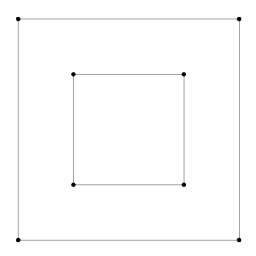
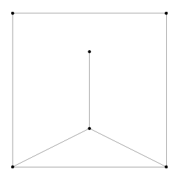
Although nothing specific in the presentation above forbids it, there is a general assumption that the two faces on either side of a given edge are not the same face, that is, every edge lies between two different faces. For rendering 3D polygon meshes, we almost certainly mean this to be the case. For a general planar subdivision isolated edges are permitted, which leads to complex questions of boundary. For example, the figure to the right has two faces, one triangle and one seven-sided face. |
|
|
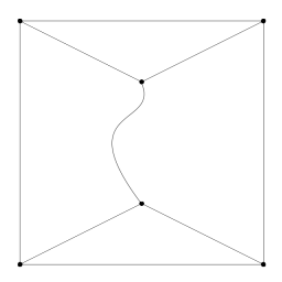
The above presentation assumes that the edge between two vertices is a straight line, but there is nothing in the underlying structure that requires that condition. We could, for example, store coordinates on each half-edge and define an edge to be the cubic Bezier curve with control points h->origin, h->coordinates, h->twin->coordinates, h->twin->origin. Similarly, faces would not necessarily have to be planar. In a usual rendering situation it is preferable to have straight edges, but again, a general planar subdivision could involve arbitrary curved edges. |
|
For some applications it may not be necessary to store and update every single pointer. For instance, if we will never be selecting a point and querying for its neighbors, we may not need to store the "leaving" pointer in vertices. Similarly, we may not need to store faces at all, if our application is more focused on the face boundaries. In most cases it is probably best to start with the full structure, then later optimize it after you are sure of which algorithms you will be using on it and which pointers they will require.
Now that we've described a DCEL data structure, let us consider why we might want to use one for 3D graphics.
Have constant time access to the neighborhood of an arbitrary point can be very useful. We can compute a normal for any given face easily, on demand, even if the vertex locations are changing. We can also traverse every face touching a vertex (the "star" of the vertex) to easily estimate a normal for that vertex. If we are locally changing small portions of a mesh, this is much easier than recomputing the normals for every vertex in the mesh. Similarly, mesh simplification for Level of Detail or compressed storage becomes easier when neighbors are easily found. Subdivision algorithms such as Loop and Catmull-Clark are relatively easy on a DCEL, especially adaptive subdivision.
When you are uncertain if the mesh you are loading or creating will be entirely triangles or will include polygons of larger size, the DCEL is a space-efficient way of holding the mesh. Every polygon in the mesh can be treated identically, rather than having to store polygon sizes and variable step sizes between polygon starts and ends.
Because a DCEL will not hold a non-manifold mesh, it can be helpful for maintaining a consistent mesh over several algorithms (e.g. triangulation followed by smoothing followed by simplification). If your algorithms are designed to work with DCEL structures they will generally avoid tearing holes or inverting random polygons.
The DCEL structure sounds wonderful! Why not use it for everything?
The DCEL structure is overkill if all you need to do is calculate normals for vertices once. If you don't need to use the strengths of the DCEL structure, look for another structure with strengths that match your needs. Keeping track of extra pointers and large dynamic sets of objects adds bookkeeping concerns and may require a good memory management subsystem to make it efficient for large meshes.
Creating and using a DCEL can use more brainpower than it is worth. If your problem doesn't require the complexity, it may be better to spend your time speeding up algorithms on an inefficient but simple structure than to spend your time rewriting them to run on a DCEL.
Generic solutions are frequently not the fastest solutions. If speed is of the essence and there is only a single algorithm you ever intend to run on a mesh, there may well be a structure that makes that algorithm much faster than it could ever be on a DCEL. Similarly, if you only have a static mesh of pure triangles that will never be modified, there is little point in converting it to a rich data structure that supports extensive modification. There are more space-efficient ways of storing pure triangle meshes that still provide reasonable time-efficiency for neighborhood queries.
The DCEL structure doesn't handle non-manifold meshes, which may rule it out entirely for some situations. It is also not very useful for large sets of unconnected (but nearby) triangles, because the neighborhood information relies on true connections between polygons. Other structures are better for finding nearest neighbor vertices that are not joined by direct edges.
Implementation issues for a DCEL are similar to the implementation issues for any complex data structure; a balance between usability, power, flexibility and speed. When implementing for use in 3D graphics there can be somewhat more emphasis on speed, but the exact balance will depend on the needs of the users.
The choice of containers for your DCEL objects is an important one. Very different choices are available, depending on the aspects of the structure that you will be using. A common implementation choice is doubly-linked lists. These allow for very easy inserting and deletion of objects, which is important for algorithms that expand or contract the mesh (Such as subdivision or simplification). Another popular choice, especially for heavily optimized or special-case implementations, is arrays. These are harder to use for insertion and deletion, but can be more memory efficient by using very organized memory techniques to calculate locations of related items by index math (e.g. storing pairs of twins on odd and even indices, thus removing the need for a separate twin pointer). These types of optimizations can be difficult to maintain through algorithm applications, and to encapsulate from the user. The array container paradigm can allow larger meshes (due to higher memory efficiency) and can be efficient for certain types of algorithms where the size of the mesh is not highly dynamic (Most non-adaptive subdivision algorithms, for instance, grow by a predictable amount per step, which could be pre-allocated).
The most frequent use of the container iterators will be iterating once through every object of a particular type (For example iterating through the faces and calculating a normal for each). The order is generally immaterial (although it may be desirable to sort by some property for other purposes) but we don't want to hit the same object twice. We often need to process every object while we are creating or modifying the DCEL structure itself, so it is unwise to depend on all pointers in the structure being correct. (For instance, doing a graph traversal of the mesh, depending on every half-edge to have a twin during the iteration process). For a minimal implementation based on doubly-linked lists, the linked list pointers may be all the iterator support you need. If you are willing to invest the time and energy into coding STL-compatible iterators, you will open up your collections to the STL algorithms, which can be helpful. Doing this efficiently is a complex design task though, and should only be undertaken if the payoff will be substantial.
Data associated with the DCEL objects is one of the most powerful aspects of the DCEL. Many complex topological problems become much easier if small amounts of data can be temporarily stored on or with objects during the processing. However, the exact type of data stored will vary drastically from algorithm to algorithm (or even from step to step of the same algorithm). The design of this subsystem, therefore, must be carefully balanced. For an expert user, a void pointer can be included with each object. This is very user-unfriendly and is inherently unsafe, but is very flexible and fast. For a more user-friendly system associated data can be stored in a separate hash table or array, indexed by unique keys stored on the objects (Which could, perhaps, be the memory address of the object itself). For data that you will absolutely always need (in your implementation) you can include it in the objects themselves. This is probably only the vertex locations and possibly normals if you intend to use your structure for rendering frequently.
The DCEL structure is complex enough conceptually without having to deal with obscure code. A primary concern in your implementation should be usability and robustness. In most cases it is worth a small slowdown if the trade-off is a higher probability of every pointer being correct. You should include routines that can check the structure for consistency for debugging. One missing next pointer can go unnoticed for several operations before suddenly bringing the entire program to a halt. It is also worthwhile to code a small, complex algorithm that uses the DCEL significantly, test it thoroughly, and use that algorithm as a basic correctness test when developing other algorithms. If the complex routine works before and after the DCEL modification, there is a good chance that the algorithm in development generates a correct DCEL.
I have written a sample implementation of the DCEL structure in C++. It uses doubly-linked lists encapsulated in a mesh container, a simple forward-only iterator scheme, and void pointer associated data. The sample code also contains code for loading and saving basic OFF files as a demonstration of how the associated data can be used for temporary storage. My mesh manipulation program MeshMan uses a variant of this code to implement a number of mesh operations, including subdivision, simplification, and tessellation.
The example code is free to use, although it would be polite to cite this page if you use it in a project of your own. I'd love to hear about bugs or simple extensions (especially if you write code for loading or saving other file types). You can see how to contact me here.
The code was written in Visual Studio, but should be relatively compatible. The included files are described below.
ExampleCode.zip 14.6KB.
|
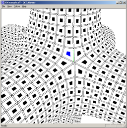
I have written a small OpenGL program utilizing the above sample implementation, DCELViewer, that loads OFF files and displays the various DCEL components. Shift+Click to select faces, half-edges or vertices and see which other objects are connected to the selected object. You can change several display colors and size properties on the menus. |
|
DCELViewer.zip 235KB. Includes DCELViewer.exe, BasicExample.off and 3DExample.off
The Half-Edge Data Structure
http://www.flipcode.com/articles/article_halfedge.shtml
An excellent description of the basic structure, with C structures and
some iteration examples for topological queries.
Halfedge Data Structure Template Library
http://geometry.poly.edu/HDSTL/doc/hdstl/table_of_contents.htm (Site appears to be dead)
Partially complete documentation, and no apparent recent updates.
Interesting implementation in template form. The design is described in the paper
Designing and implementing a general purpose halfedge data structure
by Hervé Brönnimann which is a
excellent introduction to deep implementation issues. The paper can be found
on the small page here.
(A couple of other versions can also be found on Brönnimann's sites, but this appears
to be the most complete).
CGAL - Computational Geometry Algorithms Library
http://www.cgal.org/
A powerful library for computational geometry users and researchers. Template
based and featuring support for arbitrary precision math, the learning curve
is a bit steep. It is, however, very robust and widely used by the research community.
For DCEL information in particular, see the following two starting points in the CGAL documentation:
Halfedge Data Structures in the CGAL manual.
http://www.cgal.org/Manual/doc_html/cgal_manual/HalfedgeDS/Chapter_main.html
Example of the use of a DCEL in a topological map implementation from an old version of the CGAL manual.
http://www.ics.uci.edu/~dock/manuals/cgal_manual/Topological_map/Chapter_main.html
Lutz Kettner homepage.
http://www.mpi-sb.mpg.de/~kettner/
Researcher at Max-Planck Institut fur Informatik. Previously involved
with the CGAL project, notably including the DCEL subsystem.
Computational Geometry Algorithms
and Applications: Third Edition
by M. de Berg, M. van Kreveld, M. Overmars, and
O. Schwarzkopf. Springer-Verlag, Berlin Heidelberg,
2008 ISBN: 3540779736
I have the first edition of this book. It is an excellent book with detailed descriptions of the DCEL and many of
its uses. Although I have not read the later editions, I assume they are written at the same high level of quality.
Amazon Listing
TTL: The Triangulation Template Library
http://sintef.org/Projectweb/Geometry-Toolkits/TTL/
A template-based library for triangulation and constrained triangulation. Contains a
built-in half-edge data structure.
The comp.graphics.algorithms FAQ
The Geometric Data Structures
section of the
comp.graphics.algorithms FAQ
has a good discussion of the half-edge data structure, including lucid implementation
recommendations.
Graphics Links at Holmes3D.net
Page contents copyright Ryan Holmes